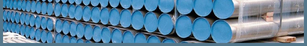
Concrete coated pipe also called concrete weight coating pipe (CWC pipe), it is the steel pipe external with concrete weight coating (Mixed with cement, aggregates, reinforced steel mesh and water), to provide the strong downward force protection or a negative buoyancy for the pipelines. This pipe is commonly used in sub-sea (submarine) pipelines, with adding the proper weight of the concrete coatings to support a resistant pressure against sea water.
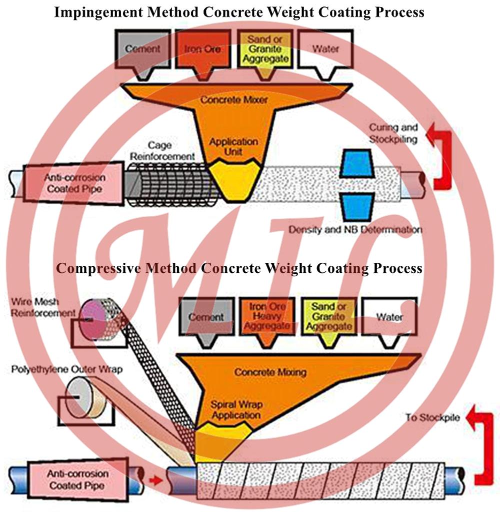
External concrete weight coating application is performed by “impingement” method. Concrete coating is applied by continuously throwing the concrete mix on longitudinally moving and rotating pipe with protective coating and installed steel reinforcing cage and/or with the use of reinforcing wire mesh. Application of concrete weight coating allows to avoid coming of pipes to the surface and provides protection from mechanical damages. Concrete is applied on factory insulating coating. Concrete application may be performed using concrete of different densities, which makes it possible for the product to comply with different project requirements. Coating thickness can vary from 20 mm to 150 mm. Concrete application provides pipe coating of uniform thickness with minimum deviations of specified weight.
Concrete weight coating is applied to the exterior of steel pipe to provide negative buoyancy or mechanical protection for submarine pipelines. Ideal for pipe ranging from 4 to 48 inched OD or greater. It can be applied over most pipe coatings. The concrete formulation can be tailored to any specified density specification. Typical product formulations are 140, 165 and 190 pounds-per-cubic-foot (nominal), but, greater densities are also available. Thicknesses can be applied from one to eight inches. Concrete compressive strengths range from 3000 psi and greater; reinforcing galvanized wire is available in several mesh and gauge values, with single or multiple feeds. Embedded depth controlled for additional strength and stability.
Application: CWC, currently the most important counter weight product in offshore pipeline , consists of cement, water, aggregates and reinforcement materials, with its characteristics such as fixing the pipeline stably on the seabed and offering effective mechanical protection for the pipeline . Compared with the pipe-in-pipe insulation, CWC is more efficient in saving steel, reducing labor force in the course of pipeline installation and lowering the operational cost.
Accurately proportioned quantities of cement, iron ore, sand and/or granite aggregate are mixed together to yield the specified density. Controlled wire placement during concrete buildup achieves the specified wire depth within the coating. Weighing verifies that each joint meets project-specific gravity requirements. Concrete ends are cleaned and excess wire is trimmed. After curing, joints are stockpiled and ready for loadout.
APPLICATION PROCEDURES FOR CONCRETE WEIGHT COATING APPLIED BY THE COMPRESSION METHOD TO STEEL PIPE
1.The intended use of this coating is to provide protection and/or negative buoyancy for buried or submarine pipelines.
2. Scope
The Applicator shall furnish all labor, equipment and material required, and shall apply the coating to all surfaces to be coated.
Protection and/or negative buoyancy, as provided under this specification, is furnished by the application of concrete weight coating to the exterior of pipe.
3. Pipe Conditions
Pipe delivered to the Applicator for coating shall be free of protective oils, lacquers, mill primer, dirt or any other deleterious surface contamination which may affect the application of the coating.
Any identification markings or stenciling on the external pipe surface shall be located on the cutback area in a transverse direction or alternatively on the internal pipe surface.
4. Handling of pipe
Proper equipment for unloading, handling and temporary storage of pipe shall be used to avoid any damage to the pipe, pipe ends or corrosion coating.
If internally coated pipe is received at the Applicator's plant, care shall be taken to avoid damage to the internal coating or the obliteration of the internal pipe markings during all phases of work covered by this specification. Internal coatings must be capable of withstanding the processing conditions necessary for the application of the concrete weight coating.
The Applicator shall visibly inspect the pipe upon receipt for damage such as dents, flat ends, bevel damage, or corrosion coating damage. Any damage observed at this point shall be noted on the inbound tally, and the Company shall be informed within 24 hours of receipt of the pipe.
5. Materials and Workmanship
All material furnished by the Applicator shall be of the specified quality. All work shall be done in a thorough workmanlike manner. The entire operation of pipe receiving, stockpiling, coating application, storage and loadout shall be performed under the supervision of and by experienced personnel skilled in the application of concrete weight coating.
6. Equipment
The Applicator's equipment shall be in such condition as to permit the Applicator to follow the procedure and obtain results prescribed in these specifications.
7. Coating Materials
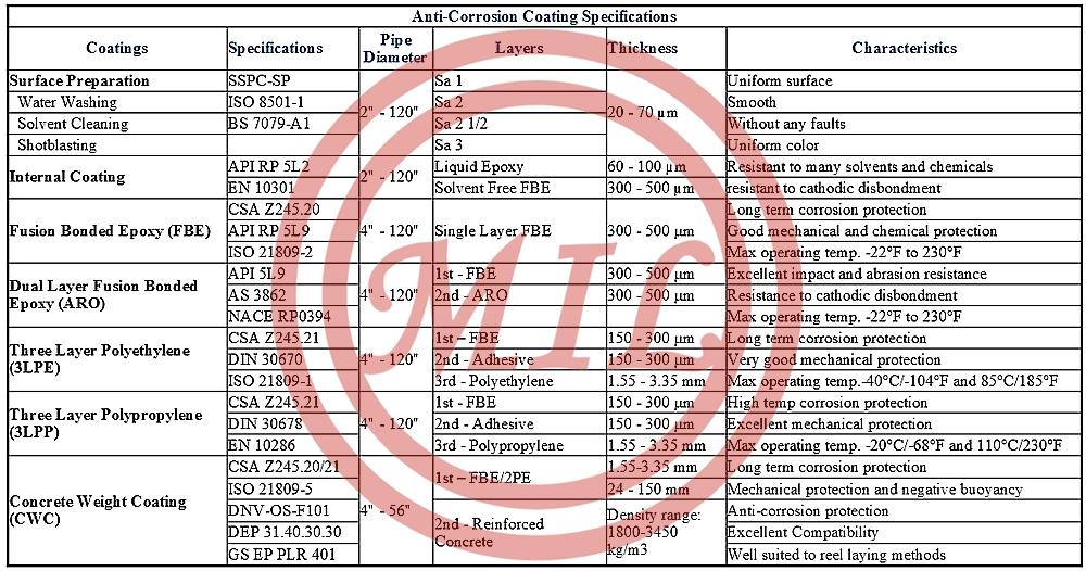
Cement
All cement shall conform to ASTM C-150, type I/II, latest revision. Cement that has hardened, partially set, or which has become lumpy shall not be used.
Heavy Aggregate
Aggregate shall be clean and free from injurious amounts of salt, alkali, organic impurities or other deleterious substances. It shall conform to the physical characteristics shown in the latest revision of ASTM C-29.
Water
Water for concrete shall be clean and free from injurious amounts of acids, alkalis, oil, sulfates or other deleterious substances. Water from doubtful sources shall be tested prior to its acceptance as a concrete ingredient, according to the latest revision of ASTM C-94, paragraph 4.1.3.1.
Sand and Gravel
Material shall be clean and free from injurious amounts of salt, alkali, organic impurities or other deleterious substances. Except for specific grading, material shall conform to the latest revision of ASTM C-33. If requested by the customer, notice of the proposed source of supply shall be given in sufficient time to permit the necessary testing of the material.
Reinforcing steel
Reinforcing steel shall be made from the best quality manufactured billet steel formed into galvanized wire fabric type reinforcing in accordance with ASTM A-810. Standard wire mesh shall be in accordance with ASTM A-82 with wires in accordance with ASTM A-185
8. Surface Preparation of Corrosion Coating
Prior to concrete weight coating, the corrosion coating shall be inspected according to the procedure in paragraph 10-G of the latest edition of NAPCA bulletin No. 13-79-94
9. Non-Slip Adhesive (Optional)
When requested by the customer, the applicator shall apply, immediately prior to the application of concrete coating, a 100% solids 2-part liquid epoxy meeting the customer’s requirements for a non-slip adhesive system.
10. Coating Application
Ingredients shall be mixed dry in the specified proportions until a homogeneous mixture is obtained. Enough water to make a cohesive grout shall then be added. After a final mixing, this mixture shall then be discharged into the coating head and applied to the pipe with the required reinforcing wire and plastic outer wrap in a continuous rotary manner. The reinforcing wire shall have a minimum overlap of 1/2" and will be cut flush with the concrete coating cutback. Concrete applied in excess of 2 3/4" thickness shall have a minimum of two layers of reinforcing wire. Concrete applied 2 3/4"or less in thickness shall require one layer of reinforcing wire. Each joint shall be free of concrete for a distance from the bevel, as specified by the customer. In no case shall any grout or concrete be allowed to remain on the inside surface of the pipe. The reinforcing wire shall not contact the corrosion coating and shall not protrude from the outer surface of the concrete coating. The outer circumference shall be smooth and free of undulations and knobs at the ends.
11. Curing
Concrete coating shall be cured for a period of not less than seven days (or until compressive strengths have achieved their minimum specified values) prior to loading out. The polyethylene outer wrap, which retains all the moisture in the applied concrete and therefore serves as the curing membrane, is to be left on the pipe until it is cured.
12. Repairs
The continuous concrete coated pipe shall be handled and stored in a manner as to minimize cracking or other damage to the concrete coating. Repairs of defects in the hardened concrete coating shall be made in accordance with the following:
An area of damage in any 5 foot run of pipe, of less than approximately 150 square inches whose depth is less than 25 % of the total concrete thickness may be accepted without repair providing the remaining concrete is sound.
Hairline cracks need not be repaired. Hairline cracks are defined as those being less than 1/16 in width and in depth less than 25% of the coating thickness.
Circumferential cracks exceeding 1/16 in width at the surface and extending more than 180 degrees around the pipe shall be repaired. Repair should be made by chiseling the crack to a width of approximately 1" throughout the length and filling with a material similar to the parent coating. The repairs shall be allowed to remain undisturbed for a period of not less than 36 hours. Longitudinal cracks exceeding 1/16 in width and 12 in length shall also be repaired.
13. Inspection and Testing
The entire procedure of applying the CWC material as herein specified will be rigidly inspected from the time the bare pipe is received until the coated pipe is loaded on the carrier for shipment.
If the Company designates an Inspector, the Inspector shall be provided free access to the Applicator’s plant at any time during any operation involving the pipe, with the right to inspect and to accept or reject work performed.
The Applicator Quality Control Inspector shall be responsible for stopping operations when conditions develop which could adversely affect the quality of the completed work.
Although the principal purpose of the coating inspection by the Company and Applicator is to insure compliance of the coating with these specifications, such inspections shall also include examination for previously undetected defects on the pipe surface or the pipe ends. Pipe having such defects shall be set aside for subsequent repair or replacement by the pipe supplier and for any necessary coating repair. Recoating or coating repair that may be necessary by reason of these defects in the pipe, which is not the fault of the Applicator, shall be done at the Company‘s expense.
When the Company's Representative exercises the Company's right of approval at the Applicator's plant, the Company's Representative shall conduct final inspection on the Applicator's weigh/inspection station. Accepted pipe shall be presumed to be produced as specified unless test results indicate otherwise.
Coating thickness measurements (diameter readings) shall be made on every pipe at 3 equally spaced locations and recorded. All thickness must lie within +/- of the specified thickness.
Applicator shall provide at the worksite, weigh scales of sufficient capacity to accommodate the weighing of the finished concrete coated pipe joint. The weigh scales shall have an accuracy of +/- 0.5%. The weight of each concrete coated pipe shall be within -5% /+7 % of the theoretical coated pipe weight in air to meet the company's requirements. Coated pipe weight shall be marked on the inside of one end of the pipe.
Applicator shall provide daily Proctor samples (4 cylinders) of concrete used in the application of the concrete coating to determine the compressive strength of this material and to compare it to the specification for compressive strength. The concrete compressive strength samples will be taken 2 times per shift in accordance with ASTM C-31 and ASTM C-39. Tests shall be conducted at 7 days and 28 days with a minimum compressive strength of 3,000 psi at 7 days.
14. Coated Pipe Handling, Storage and Loading Requirements
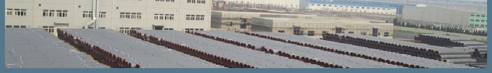
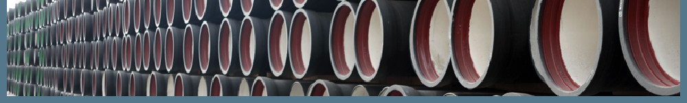
The concrete coated pipe shall be stockpiled either by laying out one high or by nesting on sand windrows. Pipes shall not be stockpiled until such time as all end cleaning and patching, if required, have been completed. Pipes may be stacked directly off the coating machine.
Pipe shall be stored, handled and transported in a manner to prevent damage to the pipe walls, beveled ends and the coating.
Sand windrows shall be so designed as to protect the coated pipe from standing water, and sharp or hard objects that might damage the coating.
CONCRETE WEIGHTED COATING REFERNCE SPECIFICATION
ISO 21809-5:2009, Petroleum and natural gas industries -External coatings for buried or submerged pipelines used in pipeline transportation systems - Part 5:External concrete coating
API 5L1 Recommended Practice for Railroad Transportation of Linepipe
API RP 5LW Recommended Practice for Transportation of Linepipe on Barges and Marine Vessels
ASTM A82 Steel Wire, Plain for Concrete Reinforcement
ASTM A185 Standard Specification for Steel Welded Wire Fabric, Plain, for Concrete Reinforcement
ASTM A615M Standard Specification for Deformed and Plain Billet-Steel Bars for Concrete Reinforcement
ASTM C33 Standard Specification for Concrete Aggregates
ASTM C39 Standard Test Method for Compressive Strength of Cylindrical Concrete Specimens
ASTM C42 Standard Test Method for Obtaining and Testing Drilled Cores and Sawed Beams of Concrete
ASTM C87 Standard Test Method for Effect of Organic Impurities in Fine Aggregates on Strength of Mortar
ASTM C125 Standard Terminology Relating to Concrete and Concrete Aggregates
ASTM C136 Standard Test Method for Sieve Analysis of Fine and Coarse Aggregates
ASTM C227 Standard Test Method for Potential Alkali Reactivity of Cement Aggregate Combinations
ASTM C294 Standard Descriptive Nomenclature for Constituents of Concrete Aggregate
ASTM C295 Standard Guide for Petrographic Examination of Aggregates for Concrete
ASTM C309 Standard Specification for Liquid Membrane-Forming Compounds for Curing Concrete
ASTM C642 Standard Test Method for Density, Absorption and Voids in Hardened Concrete
BS 1881 Methods of Testing Concrete
BS 3148 Methods of Test for Water for Making Concrete (including notes on the suitability of the water)
BS 4482 Hard Drawn Mild Steel Wire for the Reinforcement of Concrete
BS 4483 Specification for Steel Fabric for the Reinforcement of Concrete
BS 4449 Specification for Carbon Steel Bars for Reinforcement of Concrete
ISO 4012 Concrete. Determination of Compressive Strength of Test Specimen.
OFFSHORE LINE PIPE REFERENCE SPECIFICATION
API 5L PSL1/PSL 2/PSL3 Line Pipe: Gr. B X42, X46, X52, X56, X60, X65, X70, X80/BM.X42M,X46M,X52M,X60M,X65M,X70,X80M
ISO 3183-1/2/3 Petroleum and Natural Gas Industries-Steel Pipe for Pipelines-L240M,L290M,L320M,L360M,L390M,L415M,L450M,L485M,L555M,L690M
ISO 3183-3 Petroleum and Natural Gas Industries Steel Pipe for Pipelines-L245NC / L245NCS,L290NC / L290NCS, L360NC / L360NCS, L290MC / L290MCS, L360MC / L360MCS, L415MC / L415MCS, L450MC / L450MCS, L485MC / L485MCS, L555MC
DNV OS-F101 Submarine Pipeline Systems-SAWL 245,SAWL290,SAWL 320,SAWL 360,SAWL 415,SAWL 450,SAWL 485,SAWL 555
NACE MR 0175/ISO 15156-2 Petroleum and Natural Gas Industries – Materials for Use in H2S Containing Environments in Oil and Gas Production. Part 2. Cracking resistant Carbon and Low Alloy Steels, and the Use of Cast Irons.
NACE TM 0177 Laboratory Testing of Metals for Resistance to Sulfide Stress Cracking in Hydrogen Sulfide (H2S) Environments
NACE TM 0284 Standard Test Method - Evaluation of Pipeline and Pressure Vessel Steels for Resistance to Hydrogen-Induced Cracking
DEP 31.40.20.37-Gen Linepipe for critical service (amendments/supplements to ISO 3183-3)
BS 7191 All Specification for Weldable Structure Steels for Fixed Offshore Structures


 PIPE")
 PIPE")

 Offshore Pipe")
 Offshore Steel Pipe")
 Offshore Steel Pipe")


