FUSION BONDED EPOXY COATING
Fusion bonded epoxy coating, commonly referred as FBE coating is widely used to protect concrete reinforcing rebars, steel pipes, piping connections, etc used in construction.
Fusion-bonded epoxy coating principally protects against corrosion by serving as an electrochemical and a physical barrier that isolates the steel from the oxygen, moisture, & chloride ions that cause corrosion. Epoxy coating has high electrical resistance, which blocks the flow of electrons that make up the electrochemical process of corrosion. In addition to serving as a circuit breaker, the coating protects in way that is less obvious: coating reduces the size and number of potential cathodic sites, which limits the rate of corrosion reaction that could occur. As a matter of fact, for macrocell corrosion to take place, a large area of steel surface is needed to serve as the cathode where oxygen reduction can occur. The coating almost eliminates such cathodic reaction.
FBE coatings are in the form of dry powder at normal atmospheric temperature. The powder when applied electrostatically on to the surface cleaned, hot steel bars, that it fuses, melts, flows and cures to an adherent continuous chemically cross linked protective film.
PROCESS DESCRIPTION
The process of applying fusion-bonded epoxy coating to steel reinforcement involves four major steps:
1. Surface preparation.
2. Heating.
3. Powder application.
4. Cooling.
BLASTING OF BARS:
Reinforcing steel is blast-cleaned to a near white metal finish using abrasive material (shots & grits) in Shot Blaster. The shots clean the surface of the bar & grits provide an anchor (40 – 100µm) to the bar surface.
HEATING OF BARS:
The blasted bars are heated to required temperature specified by the Epoxy powder manufacturer (around 230°C) by passing them through an electric induction heater.
COATING OF BARS:
The heated bars are then passed through an Epoxy coating booth where epoxy powder is applied electrostatically. As the powder leaves the gun, an electrical charge is imparted to the epoxy powder particles. These electrically charged particles are attracted to the grounded steel surface providing a uniform coverage of the coating. When the dry powder touches the hot steel, it melts, flows, quickly gels as a film (200 –300 µm thick) on the reinforcing bars and on its deformations while the residual heat cures the coating.
COOLING OF BARS:
The coated bars after curing are passed through a cooling tunnel, where water is sprayed on to the bars to cool them. The bars are then kicked off on to the final inspection rack for testing and inspection. The testing on coated bars is carried as per ASTM775 and IS 13620 or such specification requirements. The acceptance tests usually conducted are thickness measurements, flexibility test and holiday test. Once they are inspected they are bundled/strapped for dispatch to the job site for fabrication and will be part of the structure
| MAIN TECHNICAL PARAMETERS OF Steel Rebar for concrete structures |
| Parameter |
ASTM |
BS ISO |
| A775:2007 |
14654:1999 |
| Bar Anchor Profile |
1.5-4.0 mils |
1.96-2.75 mils |
| Coating Thickness |
7-12 mils [8-16mm] |
7-12 mils |
| 7-16 mils [18-40mm] |
| Coating Holidays |
3 holidays/m(max) |
4 holidays/m(max) |
| Coating Flexibility |
180 deg. bent using 8D |
180 deg. bent using 4D&6D |
| Cathodic Disbondment Test |
Not Applicable |
Average Disbondment Radius of Three Coated Steel Reinforcing bars shall not exceed 2mm |
| Bond strength with the concrete |
Shall not be less than 85% off the uncoated bars |
Shall not be less than 85% off the uncoated bars |
| |
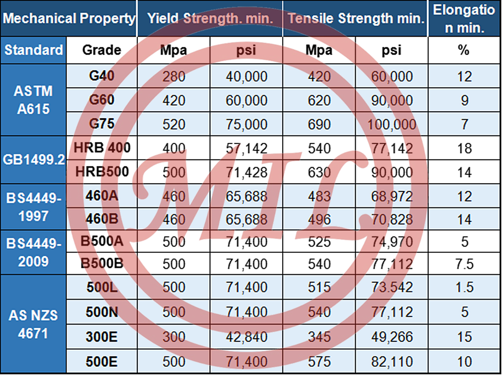
| ASTM A615 |
C% Max |
S% Max |
P% Max |
YS Mpa Min |
TS Mpa Min |
EL% GL-200 |
Bend Test |
| Grade 40 |
0.3 |
0.04 |
0.04 |
300 |
500 |
as per spc. |
as per spc. |
| Grade 60 |
0.3 |
0.04 |
0.04 |
420 |
620 |
as per spc. |
as per spc. |
| SAE 1006 |
0.08 |
0.04 |
0.04 |
210 |
350 |
as per spc. |
as per spc. |
| SAE 1008 |
0.1 |
0.03 |
0.03 |
220 |
360 |
as per spc. |
as per spc. |
| SAE 1010 |
0.13 |
0.03 |
0.03 |
260 |
400 |
as per spc. |
as per spc. |
| |
| Dimensions |
| |
| Nominal Diameter mm |
No. of Bars per bundle |
Nominal Weight kg/m |
Nominal CSA mm2 |
Spacing Max mm |
Rib Height min mm |
Max mm |
Rib Gap Max mm |
| 8 |
422 |
0.4 |
50.3 |
5.6 |
0.32 |
0.64 |
3.14 |
| 10 |
270 |
78.5 |
0.04 |
7 |
0.4 |
0.8 |
3.93 |
| 12 |
188 |
0.8 |
113 |
8.4 |
0.48 |
1 |
4.71 |
| 14 |
138 |
1.21 |
154 |
9.8 |
0.63 |
1.2 |
5.5 |
| 16 |
106 |
1.58 |
201 |
11.2 |
0.72 |
1.4 |
6.28 |
| 18 |
84 |
2 |
254 |
12.6 |
0.9 |
1.6 |
7.07 |
| 20 |
68 |
2.47 |
314 |
14 |
1 |
2 |
7.85 |
| 22 |
56 |
2.98 |
381 |
15.4 |
1.1 |
2.2 |
8.64 |
| 25 |
44 |
3.85 |
491 |
17.5 |
1.25 |
2.6 |
9.82 |
| 28 |
34 |
4.83 |
616 |
19.6 |
1.4 |
2.8 |
11 |
| 32 |
26 |
6.31 |
804 |
22.4 |
1.6 |
3 |
12.6 |